Other Tools
Selection Set Manager, Section Box Manager, Copy Revit IDs, Export and Import Properties, Explode Model and Generate Timeline.
The Other Tools panel collects the commands that do not belong to grouping, clashing or reporting but that you reach for every day: two dock panes that help you navigate the model (the Selection Set Manager and the Section Box Manager), a one-click bridge to Revit (Copy Revit IDs), a spreadsheet round trip for element properties (Export Properties and Import Properties), an exploded view of a grouping (Explode Model) and a generator that turns a selection set folder into a TimeLiner schedule (Generate Timeline).
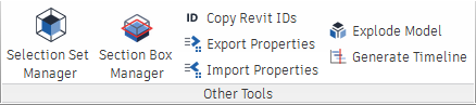
The buttons are enabled when they have something to work on:
| Button | Needs |
|---|---|
| Selection Set Manager | An open model (the pane stays empty until the model has selection sets) |
| Section Box Manager | An open model |
| Copy Revit IDs | A selection in the model |
| Export Properties | A selection in the model |
| Import Properties | An open model |
| Explode Model | A grouping made in Group Elements (not a “by source file” grouping) |
| Generate Timeline | At least one selection or search set |
Selection Set Manager
The Selection Set Manager answers the question “which sets contain the elements I have selected?”. It lists every selection set and search set of the model, folders included, and marks the ones that overlap the current selection. In the other direction, its walk modes let you click through the sets and see each one isolated or selected in the model.
It needs a model with at least one selection or search set. While the model has none, the pane’s toolbar, tree and walk-mode boxes are greyed out.
The pane at a glance
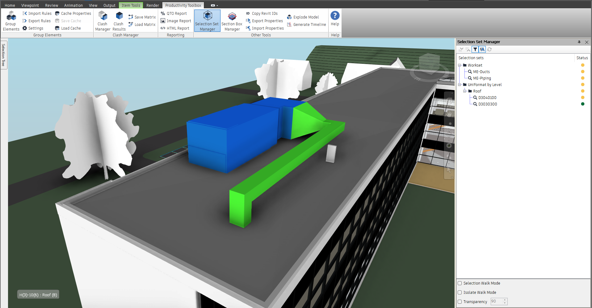
- Expand all / Collapse all: open or close every folder in the tree. The tree opens fully expanded; when the model’s sets change (a set added, renamed or deleted), the folders you had open stay open and the tree keeps its scroll position. Saving the file under another name keeps them too; opening or starting another file, or appending or unloading a model, opens the tree fully expanded again.
- Filter selection: hides every row that has no overlap with the current selection, so only the sets that contain a selected element remain. Expand and collapse are disabled while the filter is on. Switch it off to see the full tree again.
- Auto refresh: re-analyses the selection every time it changes. It is off when the pane opens; switch it on when you want the Status column to follow your clicks in the model.
- Manual refresh: rebuilds the tree from the model’s sets and analyses the current selection once. It is disabled while Auto refresh is on, because there is nothing left to refresh by hand.
- Selection Walk Mode: when ticked, clicking a row in the tree selects that set’s elements in the model (a folder selects the elements of every set below it). Unticking it clears the selection.
- Isolate Walk Mode: when ticked, clicking a row hides everything except that set’s elements.
- Transparency and its percentage box: only meaningful together with Isolate Walk Mode. When ticked, the rest of the model is not hidden but dimmed to the given transparency, so you keep the context around the set. Unticking it restores the original appearance of the model.
- The tree has two columns. Selection sets shows the folders, selection sets and search sets with their own icons (a search set has a magnifier icon, a fixed set the standard set icon). Status shows a coloured dot per row: an orange dot means “contains”, only some of the set’s elements are selected; a green dot means “equals”, the selection covers the whole set. A row with no overlap stays empty. A folder shows the green dot only when every set below it is fully selected and the orange dot as soon as one of them overlaps.
Right-click a row for the context menu:
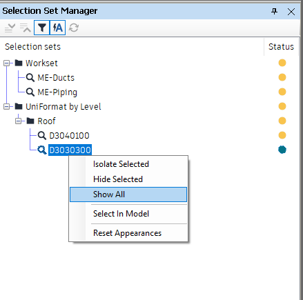
- Isolate Selected: hides everything except the elements of the highlighted rows.
- Hide Selected: hides the elements of the highlighted rows.
- Show All: shows every hidden element again.
- Select In Model: adds the elements of the highlighted rows to the current selection.
- Reset Appearances: removes every colour and transparency override, including the dimming applied by Transparency.
The menu acts on all highlighted rows at once; Ctrl-click and Shift-click work as usual.
Finding the sets an element belongs to
- Open the Selection Set Manager from the ribbon.
- Tick Auto refresh in the toolbar.
- Click an element in the model, or select several.
- Read the Status column: every set that contains at least one selected element carries the orange dot, every set the selection covers completely carries the green dot.
- Tick Filter selection to hide all other sets. With a long tree this is the quickest way to see the two or three sets that matter, and it is the state the picture above shows.
Walking through the sets
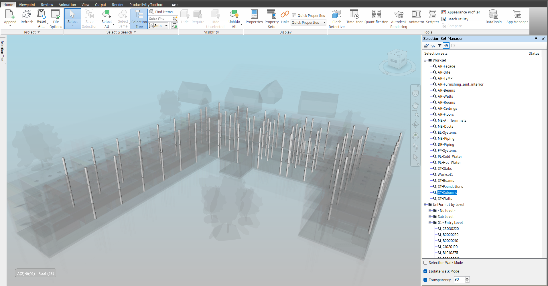
- Tick Isolate Walk Mode. Tick Transparency too if you want to keep the surrounding model visible as a ghost, and set the percentage in the box next to it (90 in the picture).
- Click a set in the tree, on its name in the Selection sets column. Only a click in that column walks; clicking in the Status column does nothing. The model shows only that set, or dims the rest.
- Click the rows one by one to walk through the sets. Selecting a row with the arrow keys moves the highlight but does not section the view, so click the row you land on.
- When you are done, untick Transparency (or right-click and choose Reset Appearances) and right-click Show All to get the whole model back.
Tips
- Both walk modes can be on at the same time: a click then isolates the set and selects its elements, ready for Copy Revit IDs or Export Properties.
- Search sets are evaluated when the pane needs them, so the first analysis after opening the pane or appending a model can take a moment on a model with many searches.
- The pane keeps working when you append or replace a model: it picks up the new document’s sets and re-evaluates the searches.
Section Box Manager
The Section Box Manager lists the Revit rooms of the model under their levels, or the levels alone, and sections the model to whichever row you click. It is the fastest way to look at one room or one storey without drawing a section box by hand.
It needs an open model. Rooms are read from the Revit room elements, so the model must have been exported from Revit with rooms included; levels come from the level property that the Revit exporter writes on every element.
The pane at a glance
- Mode: Rooms lists every level with its rooms below it; Levels lists the levels only. Changing the mode collects the model again.
- Refresh: collects the rooms or levels from the model again. The pane collects them by itself when it is first shown and after a model is appended or replaced, so you only need Refresh when you have changed the model in a way the pane did not see. The collection runs under a progress bar and can be cancelled.
- Expand all / Collapse all: open or close every level.
- Filter: type part of a room number, room name or level name; only matching rows stay visible. Matching ignores case. Clear the box to show everything.
- Clear checked: unticks every row.
- The tree has a tick box per row and four columns: Level / Room (the level name, or the room number followed by its name), Elevation (the level’s elevation, in the model’s units, levels only), Rooms (how many rooms a level holds, 0 in Levels mode because rooms are not collected there) and Geometry (yes or no: whether the row has a bounding box to section to).
- Section on click: ticked by default. Clicking the text of a row sections the model to that row. Untick it when you want to browse and tick rows without the view jumping every time.
- Zoom to fit: ticked by default. After sectioning, the camera zooms to the box.
- Section height (Rooms mode only): Room height sections a room to its own height; Level height keeps the room’s footprint but stretches the box from the level’s elevation up to the next level, so you see the full storey height including the ceiling void above the room.
- Section Checked: sections the model to one box that spans every ticked row. Ticking a level ticks its rooms as well; a ticked level already covers its rooms, so only the rooms of unticked levels are added on top.
- Clear: switches the section off, shows every hidden element and clears the selection. Closing the pane does the same when a section is still applied, so the model is back to normal when you move on.
- Select: selects, in the model, the elements behind the highlighted rows: the room elements themselves, or every element of a level. When no row is highlighted, it uses the ticked rows instead.
- The status line under the tree reports what was collected: “87 rooms on 3 levels” in Rooms mode, “6 levels” in Levels mode. It is followed by ”, 3 without geometry (export rooms from Revit with “Convert room geometry”)” when some rooms have no box, and by ”| 1 checked” while rows are ticked.
How the boxes are built
- A room’s box is the bounding box of the room element.
- Rooms mode lists only the levels that hold rooms, so the demo model shows 3 levels there and all 6 in Levels mode.
- In Rooms mode, a level’s box is the union of its rooms’ boxes; in Levels mode it is the bounding box of every element on the level.
- Levels are sorted by elevation (a “[No level]” row, when present, goes last). A level’s box runs from its own elevation up to the elevation of the next level above it, so a level cut shows exactly one storey. The highest level keeps its own top.
- Rooms under a level are sorted by room number, with numbers compared as numbers (“9” before “10”).
- Every section starts from a clean model: hidden elements are shown, any previous section is removed and the selection is cleared before the new box is applied.
Sectioning a room
- Open the Section Box Manager from the ribbon and wait for the rooms to be collected. The status line then reads, for this model, “87 rooms on 3 levels”.
- Leave Mode on Rooms, and leave Section on click and Zoom to fit ticked.
- Type part of the room number or name into Filter if the list is long, or expand the level the room sits on.
- Click the room’s row, on its text rather than on its tick box. The model is sectioned to the room and the camera zooms to it.
- Leave Section height on Room height for the room’s own height, or choose Level height and click the row again to see the whole storey height of that room.
- Click Clear to remove the section, or simply close the pane.
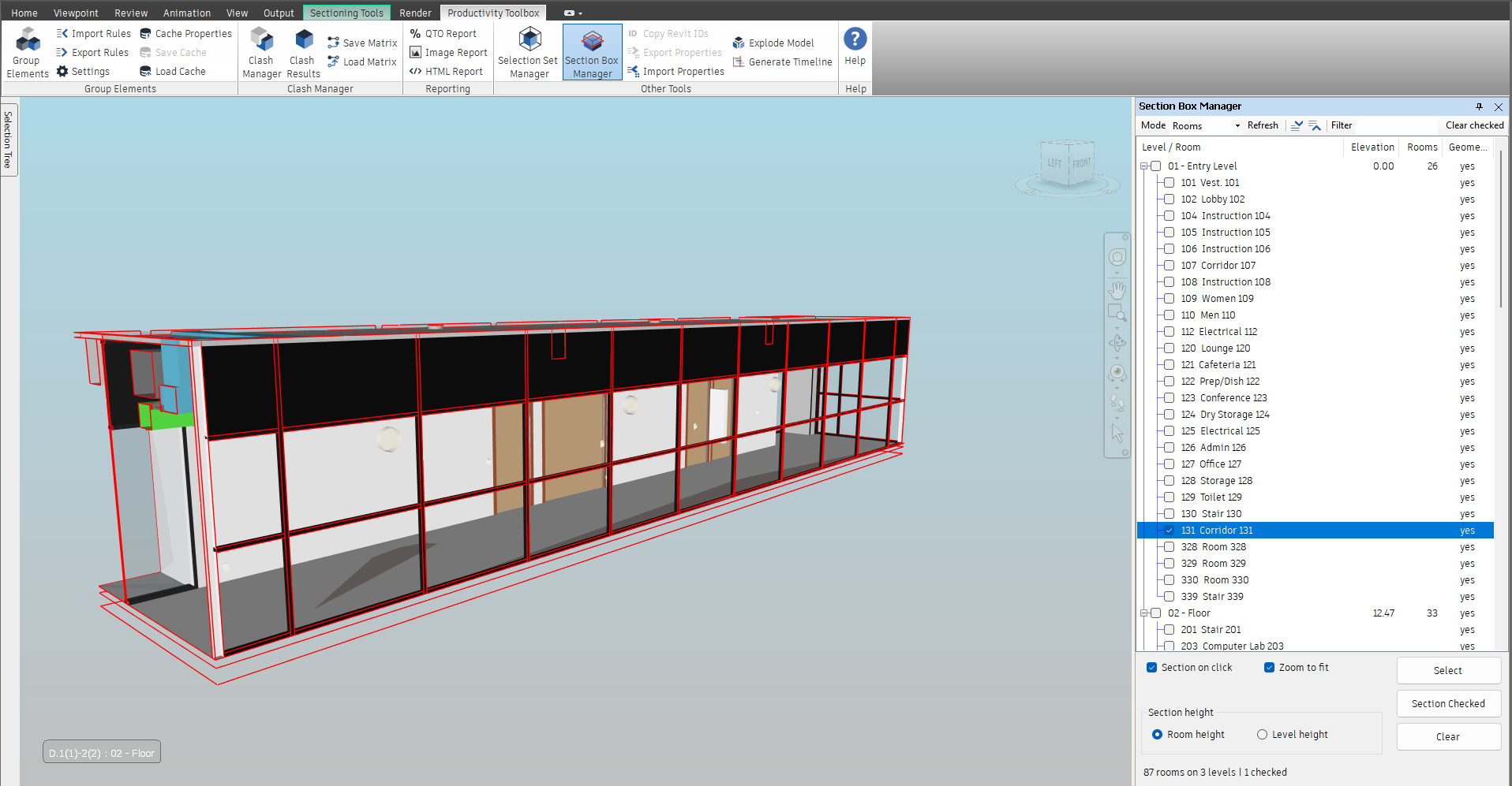
Sectioning a storey
- Switch Mode to Levels. The pane collects the levels again and lists them with their elevations, lowest first; the status line reads “6 levels” for this model.
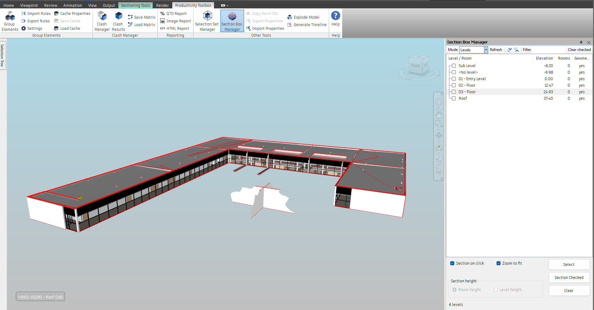
- Click a level, on its text. The section box spans the whole level from its elevation to the next level above it.
- To compare several storeys at once, tick their boxes and click Section Checked.
- Click Clear when you are done.
Tips
- Rooms with Geometry “no” cannot be sectioned (the status line says “This row has no geometry to section to.”). They were exported from Revit without room geometry. In the Revit Navisworks exporter options, tick Convert room geometry and export again.
- The section is an ordinary Navisworks section, so Navisworks’ own sectioning tools can adjust or switch it off after the pane has placed it. Navisworks shows its Sectioning Tools tab while a section is on.
- Combine Select with Export Properties or Copy Revit IDs: highlight a level, click Select, then run the export on that selection.
- Rooms without a level are grouped under “[No level]”.
Copy Revit IDs
Copies the Revit element IDs of the current selection to the clipboard as a semicolon-separated list, ready to paste into Revit’s Select by ID dialog (Manage tab). It needs a selection.
- Select the elements in Navisworks: click them, use a selection set, or click a row in the Selection Set Manager with Selection Walk Mode on.
- Click Copy Revit IDs.
- Read the message: “Done, total number of records copied: N. Number of elements without Revit ID: M”.
- In Revit, open Manage > Select by ID, paste and confirm.
Tips
- The command walks the selection and everything below it, so selecting a whole level or a file in the selection tree copies the IDs of every element inside. Elements without a Revit Element ID (for example elements from IFC or DWG files) are counted in the message and left out of the list.
- When nothing in the selection has a Revit ID, the message says “Selected elements don’t have associated Revit IDs.” and the clipboard is left unchanged.
- The list is only IDs. When you need the IDs together with other properties, use Export Properties.
Export Properties
Exports the properties you choose for every selected element to an Excel workbook or a CSV file, one row per element. It needs a selection.
The dialog at a glance
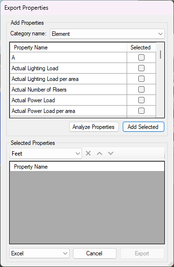
- Add Properties group:
- Analyze Properties: reads every property category and property of the selected elements and fills the Category name: list. It runs under a progress bar and can be cancelled.
- Category name:: the categories found, in alphabetical order. Choosing one fills the grid below.
- The grid lists the category’s properties (Property Name) with a Selected tick box each.
- Add Selected: moves every ticked property to the export list. A property already on the list is not added twice.
- Selected Properties group:
- The units drop-down at the left of the small toolbar chooses the unit that length values are converted to. It starts on the model’s own units, Feet for the demo model.
- The cross button next to it removes the highlighted property from the list; the up and down arrow buttons move it, which changes the column order in the file.
- The grid lists the properties to export in column order, each as
[Category,Property]. - The file type drop-down below the grid chooses Excel or CSV.
- Export: asks where to save the file (the dialog is titled “Save to Excel File” or “Save to CSV File”), builds the table under a progress bar and opens the file when it is written. Export is only enabled once the list holds at least one property.
- Cancel: closes the dialog without exporting.
What the file contains
- One row per selected element and every element below it in the selection tree, down to the geometry level; group nodes, layers and file nodes are skipped.
- The first column is GUID, the element’s unique identifier in Navisworks.
- Then one column per exported property, headed
[Category,Property], for example[Element,Mark]. Import Properties understands this header, so the file can be edited and imported back. - Length values are converted to the chosen export unit; integers stay integers; everything else is written as text. A property that is a number on some elements and text on others makes a text column, with the numbers written in it as text. Numbers are written the same way whatever the Windows language, so a file made on one machine imports on another.
- In the Excel workbook, a header that differs from an earlier one only in upper and lower case
gets a number appended, as Excel does with repeated headers (for example
[Element,Reynolds Number]2). Import Properties ignores such a column. - The Excel workbook holds a single data sheet, named Properties Export, with the table starting one row down and one column in; the CSV file is a plain comma-separated file that opens in Excel.
Exporting properties of a selection
![Three properties on the export list, [Element,Mark], [Element,Name] and [Element,Length], with the units set to Millimeters and the file type Excel; Length is still ticked in the grid above.](/guide/images/46-exportprops-dialog-filled.png)
- Select the elements in the model.
- Click Export Properties.
- Click Analyze Properties and wait for the progress bar.
- Pick a category under Category name:, Element in the picture, tick the properties you need, here Mark, Name and Length, and click Add Selected. Repeat for other categories.
- Order the list with the up and down arrow buttons; remove mistakes with the cross button.
- Choose the export units, Millimeters in the picture, and the file type, Excel.
- Click Export, choose a file name in the Save to Excel File dialog and wait. The file opens when it is ready.
![The exported workbook, sheet Properties Export: the GUID column followed by [Element,Mark], [Element,Name] and [Element,Length], with the lengths in millimetres.](/guide/images/47-exportprops-excel.png)
Tips
- Analyse on a representative selection: a category that no selected element carries does not appear in the list.
- The export can be cancelled from the progress bar; nothing is written in that case.
- Properties that are unique by display name and data type appear once even when they come from several source files.
Import Properties
Writes values from an Excel workbook onto the matching model elements as user-defined properties. Typical uses: adding a status, a cost code or a delivery date per element from a spreadsheet, or round-tripping an Export Properties file after editing it. The button is always enabled; the dialog works on the whole model or on the current selection.
The dialog at a glance
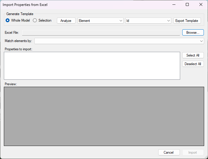
- Generate Template group:
- Whole Model / Selection: the scope, used both for the template and for matching during the import.
- Analyze: reads the categories and properties of the scope so you can pick the identifier. When you have run Cache Properties or Load Cache (Group Elements panel), the two lists are already filled when the dialog opens and you can skip this.
- The category and property drop-downs: the property whose values identify an element, for example Element / Mark or Element / Id.
- Export Template: writes a workbook named
Import_Template.xlsxby default, with an Import Template sheet holding one row per element of the scope that has a value for the chosen property, plus an Instructions sheet. It runs under a progress bar and can be cancelled (nothing is written then). The file opens when ready.
- Excel File: and Browse…: choose the workbook (
*.xlsx) to import. Only the first worksheet is read. Its first filled row is the header row, wherever the table starts (an Export Properties workbook starts one row down and one column in); the dialog reads it and fills the lists below. - Match elements by:: the column whose values identify the element. It lists every column with a valid header; the first one is preselected.
- Properties to import:: every other column, ticked by default. The GUID column of an Export Properties file is not listed: it only identifies elements. Select All and Deselect All tick or untick them all. Untick the columns you do not want written.
- Preview:: the first 20 data rows of the workbook, so you can check that the right sheet and the right columns were found.
- Import: enabled once a file is chosen; runs the import and shows a summary.
- Cancel: closes the dialog.
Header format
Every column the importer should use needs a header in one of these three forms:
Category/Property, for exampleElement/MarkorStatus/Installed[Category,Property], the form Export Properties writesGUID, the first column of an Export Properties file. It is offered asItem/GUIDand matches each element by its own GUID, the value Navisworks shows under Item / GUID.
Columns with any other header are ignored. When no column has a valid header the dialog says “No valid Category/Property headers found.” The category part names the property tab the value goes to; the property part names the property in that tab.
Round trip: export, edit, import
- Select the elements (or plan to import into the whole model) and click Import Properties.
- Choose Whole Model or Selection, click Analyze if the drop-downs are empty, and pick the identifier, Element and Id in the pictures.
- Click Export Template, save the file (
Import_Template.xlsxby default) and let it open. The single column is the identifier, headedElement/Id; every row is one element. The second sheet, Instructions, repeats these rules. - In Excel, add one column per property you want to write, headed
Category/Property, for exampleStatus/InstalledorCost/Code. Fill in the values; leave a cell empty when an element should not get that value. Save the workbook and close it. - Back in the dialog, click Browse… and pick the workbook.
- Check Match elements by: shows the identifier column and that the added columns are ticked under Properties to import:. Look at Preview:.
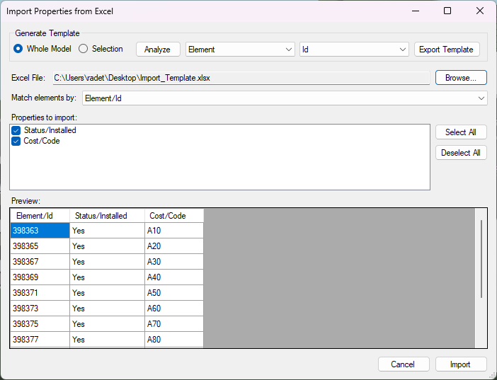
- Click Import. The progress bar first matches the elements, then writes the rows. You can cancel at any time; what was written so far is kept.
- Read the summary. It opens with “Import complete.” (or “Import stopped; what had been written so far is kept.” after a cancel) and then lists “Elements matched”, “Elements not found” (rows whose identifier matched no element in the scope), “Properties written” and “Errors”.
- Select an element and look at the Navisworks Properties window: the new tab, named after the category in the header, Status or Cost for the columns above, holds the imported values.
The same steps work with a file made by Export Properties: keep the GUID column (or any other exported column) as the identifier, edit the other columns and import.
What gets written and how
- Values land in a user-defined property tab named after the category. Native Revit properties are never overwritten; when the category name equals a native one (for example “Element”) a user tab with that name is created next to it.
- When the tab already exists on the element, its other properties are kept and only the imported properties are replaced.
- An empty cell writes nothing, so the element keeps whatever it had.
- A row with an empty identifier cell is skipped. When several elements share the same identifier value, all of them receive the row’s values.
- Cells are typed by what they contain: whole numbers and decimals become numbers, “true” and “false” become yes/no values, recognisable dates become dates, everything else stays text. Text with a leading zero, such as “0012”, is kept as text so a mark or a room number is not turned into 12; a date such as 06.10.2026 still becomes a date.
- Identifiers are compared as text after normalising numbers, so a cell showing “1,5” still matches an element whose value is 1.5, whatever the Windows language.
- After the import, the analysed property lists are refreshed so the new properties show up the next time you analyse or group by property.
Tips
- Close the Navisworks Properties window before a large import; it reacts to every change and slows the import down considerably.
- Choose an identifier that is unique per element (Element / Id, the GUID column of an export, or a well-maintained Mark). A duplicated identifier writes the same values onto every element that carries it.
- Run the import on Selection when the workbook only concerns a part of the model: matching a few thousand elements is much faster than indexing the whole model.
- Imported properties are saved with the NWF/NWD like any other user-defined property, and Group Elements can group by them.
Explode Model
Spreads the groups of a grouping apart along up to three axes, one axis per grouping level, so you can inspect the breakdown: by level, by workset, by category. It needs a grouping created in the Group Elements pane; a grouping whose rules include “by source file” cannot be exploded and does not appear in the list.
The dialog at a glance
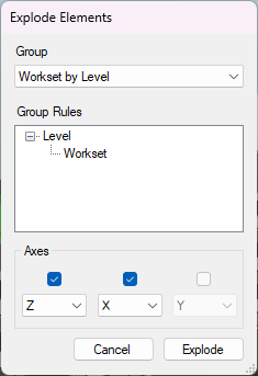
- Group: the grouping to explode, from the groupings listed in the Group Elements pane. The first one is chosen when the dialog opens, “Workset by Level” in the picture.
- Group Rules: shows the grouping’s rules as a chain, the first rule at the top and every further rule one step further in: Level with Workset under it in the picture. Each rule corresponds to one row under Axes.
- Axes: three rows, one per grouping level. Tick the box on a row to explode that level and pick the axis (X, Y or Z) from its drop-down. The drop-downs start on X, Y and Z from the top and stay greyed until their row is ticked. The second row is only available once the first is ticked and the grouping has at least two levels; the third once the second is ticked and the grouping has three. Each axis can be used once: picking an axis that another row already uses swaps the two, which is why choosing Z on the first row and X on the second leaves Y on the third.
- Explode: enabled once the first row is ticked; runs the explode.
- Cancel: closes the dialog.
What happens
For every ticked level, the groups of that level are pushed apart along the chosen axis. The distance between neighbours is the size of the largest group of that level along that axis, so the groups never overlap. The first group stays where it is, the second moves by one step, the third by two, and so on; the next level repeats this inside each group along its own axis.
The command runs under a progress bar in two stages, “Measuring group sizes…” and “Moving N group(s)…”, and can be cancelled. A cancelled run asks “Reset the transforms applied so far?”: answer Yes to put the groups moved so far back, or No to keep the partial explode.
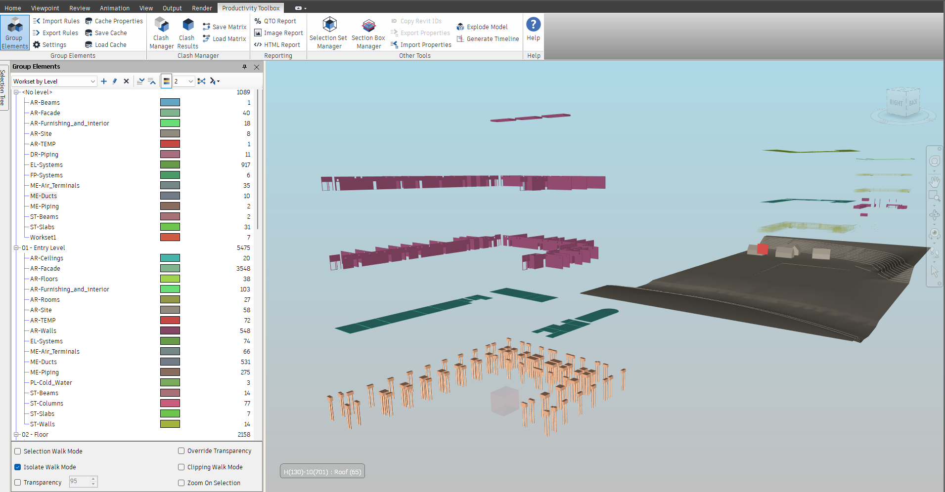
Exploding a model by level and workset
- In Group Elements, create a grouping with two rules, Level then Workset, and let it run. It appears in the pane’s grouping list as “Workset by Level”.
- Click Explode Model.
- Choose the grouping under Group, “Workset by Level” in the picture, and check the chain under Group Rules.
- Tick the first row under Axes and choose Z, so the levels are stacked apart vertically.
- Tick the second row and choose X, so the worksets on each level are spread sideways. Leave the third row unticked.
- Click Explode and wait for the progress bar.
- When you are done, open the Group Elements pane, right-click and choose Reset Transforms to put everything back.
Tips
- Explode moves elements with transform overrides; nothing in the model files changes. Reset Transforms in the Group Elements pane, or Navisworks’ own Reset All > Transforms, removes the offsets.
- A level with no groups, or whose groups have no geometry, measures zero and is simply left where it is.
- Explode the levels along Z and the rest along X or Y for the most readable result; exploding two levels along the same axis is not possible.
Generate Timeline
Builds a TimeLiner task tree from a selection set folder: every folder becomes a summary task and every set becomes a task attached to that set, so the simulation follows the sets even when their contents change later. A sequence blueprint decides the order in which the tasks are built, and the planned dates are laid out from a start date. It needs at least one selection or search set.
The natural input is a folder exported from Group Elements (for example a grouping by level and UniFormat code saved as selection sets), but any folder structure works.
The dialog at a glance
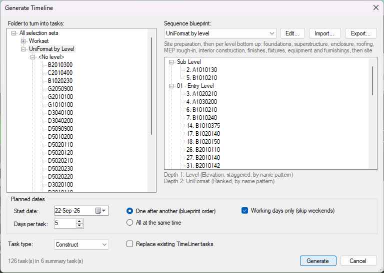
- Folder to turn into tasks:: the model’s selection set tree, with All selection sets at
the top. Highlight the folder (or a single set) to convert, “UniFormat by Level” in the
picture; under it sit one folder per level (
<No level>, “Sub Level”, “01 - Entry Level” and so on) and, in each, one set per UniFormat code. The preview on the right updates with every click. - Sequence blueprint:: the ordering rules. Three blueprints are built in:
- UniFormat by level: site preparation first, then per level from the bottom up: foundations, superstructure, enclosure, roofing, MEP rough-in, interior construction, finishes, fixtures, equipment and furnishings, then site improvements. The levels are staggered so the structure of every level is done before the fit-out of any level starts. Rooms, masses, topography, rebar, grids, levels, views and similar are marked as not built.
- Revit categories by level: for models without assembly codes; per level from the bottom up, Revit categories in trade order (foundations, structure, exterior walls, roofs, MEP, partitions, finishes, fixtures, furniture).
- Folder order: no reordering; tasks follow the tree exactly as it is. Your own saved blueprints are listed after the built-in ones, and blueprints imported from files after those.
- Edit…: opens the blueprint editor (see below) on the chosen blueprint.
- Import… / Export…: load a blueprint from a
.jsonfile into the list, or write the chosen blueprint to a.jsonfile to share it. - The description under the list explains the chosen blueprint.
- The preview tree shows the resulting task tree in build order. Each set carries its position in the sequence (“1. ”, “2. ”, …); folders and sets marked as not built are greyed and suffixed “(not built)”. The numbers jump from folder to folder when a dimension is staggered, as in the picture, where “Sub Level” holds tasks 2 and 5 and “01 - Entry Level” tasks 3, 4, 6 and 7.
- The bindings text under the preview says how each depth of the folder was understood, for example “Depth 1: Level (Elevation, staggered, by name pattern)” and “Depth 2: UniFormat (Ranked, by name pattern)” in the picture, or “Depth 3: not matched, folder order kept” when no dimension recognises a depth.
- Planned dates group:
- Start date:: the day the first task starts. It opens on today’s date.
- Days per task:: the duration of every task, 1 to 365 days (default 5).
- One after another (blueprint order): each task starts when the previous one ends, in the order the preview shows.
- All at the same time: every task gets the same start and end.
- Working days only (skip weekends): ticked by default; Saturdays and Sundays are skipped when counting days, and a start date on a weekend moves to the Monday.
- Task type:: Construct, Demolish or Temporary, applied to every task; Construct when the dialog opens.
- Replace existing TimeLiner tasks: unticked by default. When ticked, every task already in TimeLiner is deleted before the new tree is added; when unticked, the new tree is added after the existing tasks.
- The summary line at the bottom left reads “N task(s) in M summary task(s)”, “126 task(s) in 6 summary task(s)” in the picture, followed by ”, K not built” when the blueprint excludes some of them.
- Generate: enabled when the chosen folder holds at least one set; creates the tasks and reports “N task(s) in M summary task(s) created, <start> to <finish>.” with a note on tasks that are disabled because the blueprint marks them as not built.
- Cancel: closes the dialog.
What the tasks look like
- One summary task per folder, named after the folder; its dates span its children.
- One task per set, named after the set, with the set attached as its selection. Its Display ID is the task’s position in the build sequence.
- Every task runs from 08:00 on its first day to 17:00 on its last day.
- Tasks for names on the blueprint’s not-built list are created but disabled, so they do not animate, and take the dates of their built siblings.
Generating a timeline from an exported grouping
- In Group Elements, create a grouping by Level and UniFormat (assembly code) and save it to selection sets; a folder named after the grouping, “UniFormat by Level”, appears in the selection set tree, with one sub-folder per level and one set per code.
- Click Generate Timeline.
- Highlight that folder under Folder to turn into tasks:.
- Leave Sequence blueprint: on UniFormat by level and check the bindings text under the preview: it should read “Depth 1: Level (Elevation, staggered, by name pattern)” and “Depth 2: UniFormat (Ranked, by name pattern)”.
- Look through the preview tree and confirm that the order makes sense: foundations before structure, structure of the lower level before the upper one, finishes last.
- Set Start date: and Days per task:, 5 days in the picture, and keep One after another (blueprint order) and Working days only (skip weekends).
- Leave Task type: on Construct, or choose another one, and tick Replace existing TimeLiner tasks if the TimeLiner should hold only this schedule.
- Click Generate and read the confirmation.
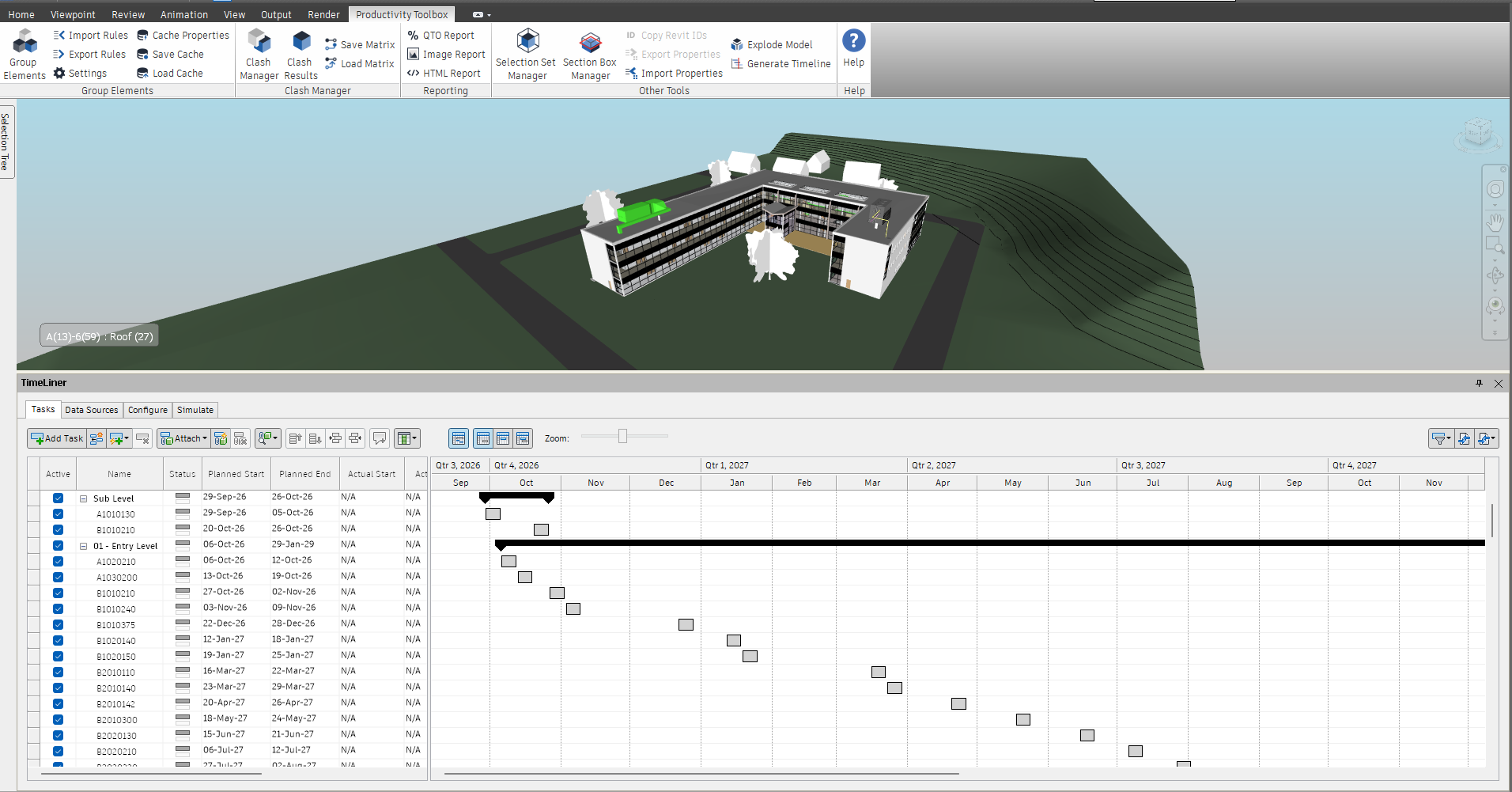
- Open the Navisworks TimeLiner window and its Tasks tab: the task tree is there, with the sets attached. Adjust durations and dates in TimeLiner as needed and run the simulation.
How a blueprint orders the tree
A blueprint is a list of dimensions, one per level of the breakdown (Level, UniFormat, Category, …). Each dimension has:
- Recognisers that tell it which depth of the folder it applies to. A
propertyrecogniser matches the name of the grouping rule that produced the folder (Group Elements writes it into the folder name, “Level/Element/UniFormat/Category”); aregexrecogniser matches when most folder names at a depth fit a pattern; alistrecogniser matches when most names are on a fixed list. Depths that no dimension recognises keep their folder order. When the exported folder carries the grouping’s own name rather than the rule path, as “UniFormat by Level” does, theregexandlistrecognisers do the work, and the bindings text says “by name pattern” instead of “by grouping rule”. - A Sort: AsIs (folder order), Natural (alphabetical with numbers compared as numbers), Elevation (by the height of the elements, lowest first) or Ranked (by the position of the name in the dimension’s rank list).
- A Rank order for the Ranked sort: patterns such as
B1010*orWalls, in build order.*is a wildcard, matching ignores case, and when several patterns match a name the most specific one wins. - Unmatched go:: where names that match no rank pattern go: Last, First or Exclude (the task is still created but disabled).
- Staggered: work the dimension’s values in parallel: the sequence walks the next dimension first, so with Level staggered the structure of every level comes before the enclosure of any level.
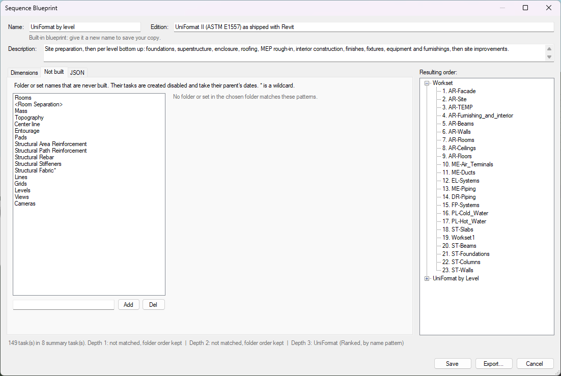
On top of the dimensions, the blueprint’s Not built list names folders or sets (wildcards allowed) that are never built; their tasks are created disabled and take their parent’s dates.
Editing a blueprint
The editor opens from Edit… and checks every change live against the folder chosen in the Generate Timeline dialog, so you see immediately which depth each dimension binds to, how many values every rank pattern catches, and what the resulting order is. The three pictures below were taken with All selection sets highlighted rather than one exported folder, which is why the resulting order starts with the “Workset” folder and the status line says depths 1 and 2 are not matched.
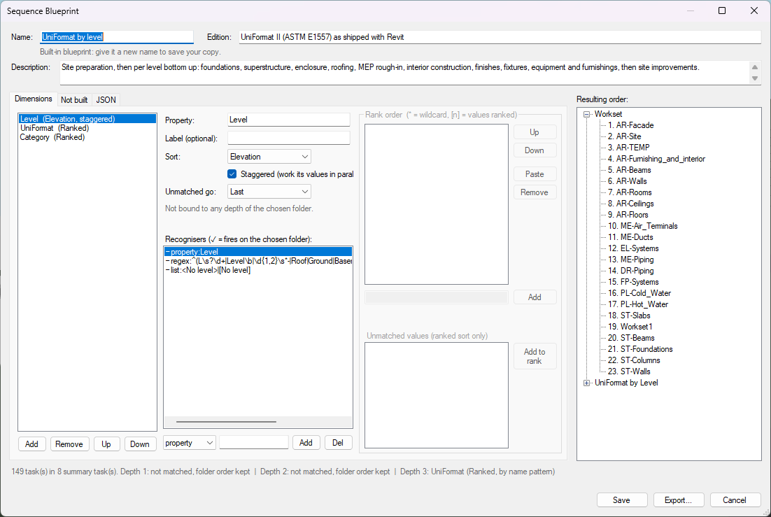
- Name:, Description:, Edition:: the header. A built-in blueprint shows the note “Built-in blueprint: give it a new name to save your copy.” and cannot be overwritten. Edition: names the code list the blueprint was written against, “UniFormat II (ASTM E1557) as shipped with Revit” for the built-in UniFormat blueprint.
- Dimensions tab:
- The list on the left shows each dimension as “Label (Sort, staggered)”, so “Level (Elevation, staggered)”, “UniFormat (Ranked)” and “Category (Ranked)” for the built-in UniFormat blueprint. Add appends a new dimension, Remove deletes the selected one (the last dimension cannot be removed), Up and Down reorder them.
- Property: the name of the dimension, which is also what a
propertyrecogniser looks for; Label (optional): the display text; Sort:; Staggered (work its values in parallel); Unmatched go:. A summary line says “Bound to depth 2 by name pattern: 38 value(s), 35 ranked, 3 unmatched”, or “Not bound to any depth of the chosen folder.” as in the picture, where the chosen folder has no depth of level names. - Recognisers (✓ = fires on the chosen folder): the list, with a tick in front of the
recogniser that bound the dimension, and no tick at all when none of them fires. Pick the
kind (property, regex or list) in the small drop-down, type the argument and
click Add; Del removes the selected one. The Level dimension of the built-in
blueprint carries one of each:
property:Level, aregex:for names such as “L2”, “Level 2”, “02 -”, “Roof” or “Ground”, and alist:for<No level>. - Rank order ( = wildcard, [n] = values ranked)**: every pattern with, for UniFormat codes, its title (for example “B2010 Exterior Walls”) and the number of values it catches in brackets (a dot when it catches none). Type a pattern and click Add to insert it after the selected one; Paste inserts one pattern per line, comma or semicolon from the clipboard; Remove, Up and Down edit the list. Selecting a pattern lists the values it ranks underneath.
- Unmatched values (N): the values of the bound depth that no pattern catches. Highlight one or more and click Add to rank to insert them as patterns. The list is only filled for the Ranked sort; for any other sort it is empty and headed “Unmatched values (ranked sort only)”, as in the picture.
- Not built tab: the exclusion patterns, with a box, Add and Del under the list, and
a line saying which names of the chosen folder they currently match. The built-in list names
Rooms,
<Room Separation>, Mass, Topography, Center line, Entourage, Pads, Structural Area Reinforcement, Structural Path Reinforcement, Structural Rebar, Structural Stiffeners, Structural Fabric*, Lines, Grids, Levels, Views and Cameras.
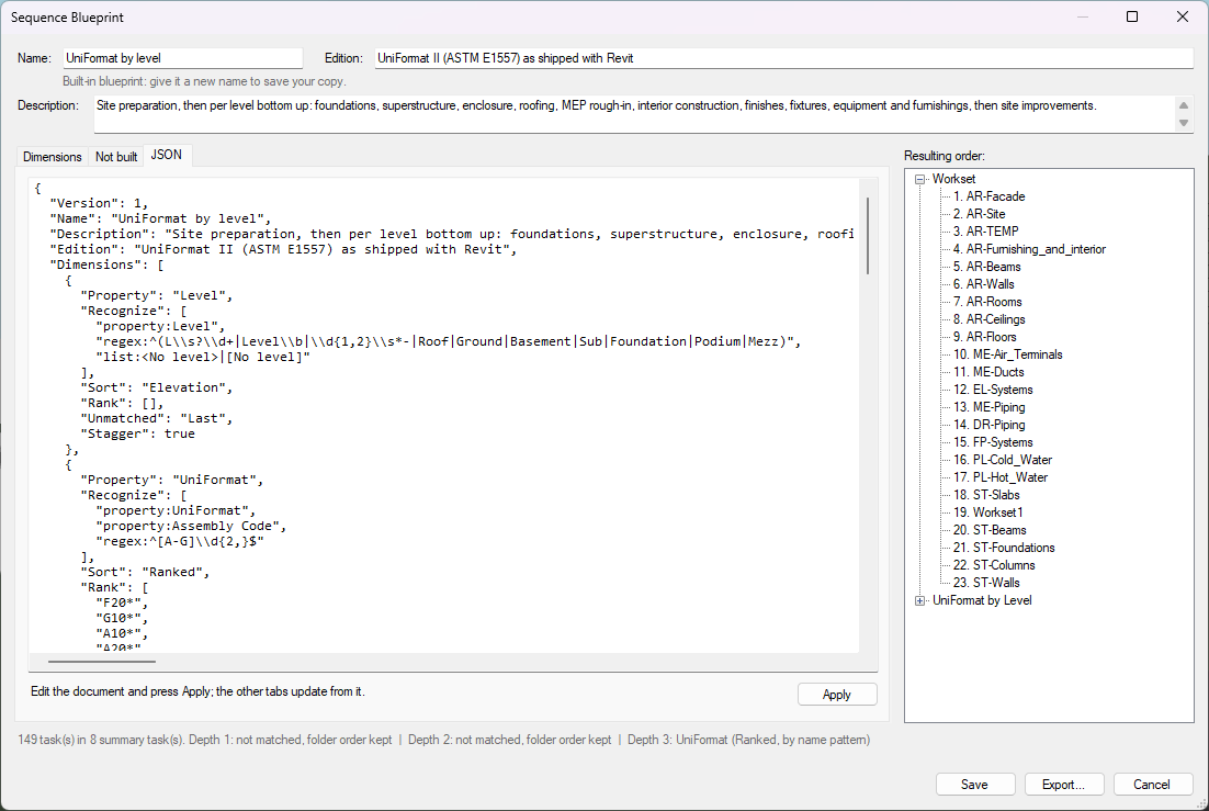
- JSON tab: the whole blueprint as text. Edit it and click Apply; the other tabs update from it, and an invalid document is reported in red without changing anything. The line under the box reads “Edit the document and press Apply; the other tabs update from it.”
- Resulting order: on the right is the same preview as in the main dialog, updated after every change. The status line under it joins the two: “149 task(s) in 8 summary task(s).” followed by the depth bindings separated by vertical bars.
- Save: stores the blueprint under its Name: in your user profile and selects it in the main dialog. A blank name is refused; a built-in name is refused (“Choose another name to save your copy.”); an existing name of your own asks whether to replace it. Renaming a stored blueprint replaces the old file.
- Export…: writes the blueprint to a
.jsonfile without storing it. - Delete: only shown for a stored blueprint; removes it after a confirmation.
- Cancel: discards the changes.
Typical edit: open UniFormat by level, select the UniFormat dimension, look at Unmatched values, add the codes your model uses that the list does not know (with Add to rank) and move them to the right place with Up and Down; then give the blueprint a new name and click Save.
Tips
- Every task gets the same Days per task: duration; per-phase durations are not supported yet and are planned for a later release. Adjust individual durations in TimeLiner afterwards.
- When the bindings text says “not matched, folder order kept” for a depth you expected to be
ordered, open the editor: the Recognisers list shows which recogniser fires, and a
regexorlistrecogniser can be added for your naming convention. - Replace existing TimeLiner tasks deletes every task in TimeLiner, including ones you made by hand or imported from a schedule. Leave it unticked to append instead.
- Choose a single set instead of a folder to create one task.
- Search sets are attached like selection sets, so a task built from a search follows the search when the model is updated.
- Blueprints are plain JSON files; Export… and Import… move them between machines, and a saved blueprint is listed in every model you open.
Something unclear or out of date in this chapter? Write to [email protected].